The Case for Four Phase Power

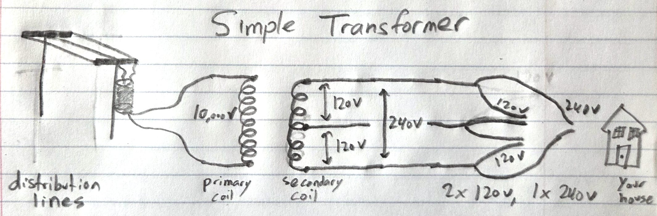
Residential transformers step down from distribution line voltage (usually around 13,000V) to 240V. The secondary coil has a center tap, which gives you two 120V halves. Tap the top half of this coil for a bedroom circuit. Tap the other half for the kitchen. Both of them get 120V. Tap across the whole coil to power your washing machine with 240V, as shown in the drawing below:
Industrial transformers are usually 480V, and they have three phases instead of one. Three-phase power means three conductors, each carrying current in a sine wave, each offset from the other two by 120°. If you picture a clock face, the three phases point at 12, 4, and 8. When the three coils are connected at a common neutral point, the configuration is called wye, as it physically looks like the letter Y. Each phase’s voltage rises and falls 120° offset from the others. All three carry current at all times, and because the peaks are staggered, total power delivered to a balanced load stays nearly constant rather than pulsing. You can use all three phases together to run a 480V three-phase motor, which is incredibly common in industrial settings, and was the original reason for developing three-phase. Or you can tap any one of the three phases to the neutral wire at the center of the wye (where the coils meet) and get 277V.
What an unusual voltage! For any AC system, where VLN is line-to-neutral voltage, VLL is line-to-line voltage, and θ is the angle between phases:
For three-phase,
So a 480V three-phase system has a line-to-neutral voltage of 480 ÷ √3, which is 277V single-phase. This is where 277V comes from. It is not a naturally chosen load voltage; it occurs due to the geometry of a 480V wye system. Over time, though, 277V became very useful because commercial lighting, breakers, panels, and electrical practice standardized around it.
The same thing happens at lower voltages. A 208/120V system is three-phase with 120V line-to-neutral. Multiply 120V * √3, and you get 208V when using all the conductors. Unfortunately, 208V cannot power equipment designed strictly for 240V. 208V is 13% lower than 240V, and as we know, power is proportional to voltage squared. 13% lower voltage ≈ 25% less power. Buildings running 208V systems cannot use standard 240V appliances without a boost. For resistive loads, the result is lower power: a 240V heater run at 208V produces about 25% less heat. Motors are more complicated. If a motor is asked to deliver the same mechanical load at lower voltage, it may draw more current to make up for missing volts, meaning it will run hotter or struggle to start.
Four-Phase Proposal
What I am here calling four-phase is very similar to Nikola Tesla’s two-phase, and it predates three-phase commercial power. Tesla’s original polyphase patents in 1888 used two windings 90° apart. The Niagara Falls hydroelectric plant came online in 1895, generating two-phase power, and in 1896 transmitted electricity about 25 miles to Buffalo, the decisive demonstration of long-distance AC transmission and the moment AC won the War of the Currents against Thomas Edison’s DC. Philadelphia ran a two-phase distribution network starting in the same era. Parts of it are still in service today: PECO continues to supply legacy two-phase power to certain Center City buildings, as does the utility in Hartford, Connecticut. The two-phase service is now synthesized from three-phase service using Scott-T transformers, but the building wiring and many of the loads are original.
The reason this is called “two-phase” rather than “four-phase” is that phases 180° apart aren’t electrically independent. One phase is just the inverse of the other. A four-wire 90° offset system has four conductors but only two independent phases.
Three-phase displaced two-phase for good reasons: for long-distance transmission and large motors, three-phase delivers the same constant power with three conductors instead of four (less copper per watt), and three-phase generators are mechanically simpler. By the early 1900s, three-phase had won almost everywhere it competed.
The case for revisiting four-phase is about the last hundred feet of distribution inside modern mixed-use buildings, where the cost-benefit calculation looks different than it did in 1895.
A four-phase system spaces its conductors 90° apart instead of 120. With the clock analogy from earlier, phases are at 12, 3, 6, and 9. There are four sine waves, each offset 90° from the next, so their peaks are staggered. Here are the outcomes of tapping any two of the four phases in a 480V system:
Phase 1 & Phase 2: 339V (90°)
Phase 1 & Phase 3: 480V (180°)
Phase 1 & Phase 4: 339V (90°)
Any Phase & Neutral: 240V
Note that tapping phase 1 & 2 is electrically the same as tapping phases 2 & 3, 3 & 4, and 4 & 1.
So, adding an extra phase removes the need for another transformer stepping down from 480V three-phase to 240V single-phase. The downside is that commercial lighting often uses 277V, but this is a product of 277V being a natural neutral tapping point for 480V rather than having some intrinsic importance. There is already a massive ecosystem surrounding 277V, but commercial lighting and other 277V systems could just as easily use 240V or 339V if there was enough demand.
To clarify, this is not a proposal that four-phase would replace three-phase in most cases. Three-phase won for excellent reasons: smooth rotating power with the fewest conductors possible, uses less copper and switchgear than four-phase, and has 100 years of motors, transformers, breakers, panels, and meters built around it.
The deeper benefit of four-phase is architectural simplicity. A four-phase panel would not need to choose between being voltages “good for receptacles” and “good for industrial loads.” The same bus geometry would support both. Instead of treating 240V as a special case requiring a transformer, it becomes a native voltage.
It also gives designers more useful choices. Opposite phases give full voltage. Adjacent phases give an intermediate voltage. Phase-to-neutral gives the ordinary equipment voltage. The panel contains several usable voltage classes without extra magnetic hardware.
Four-phase would also improve voltage symmetry for distribution. Residential split-phase is useful but not rotational. Three-phase is rotational but produces awkward derived voltages. Four-phase combines the useful part of split-phase with the useful part of multiphase power: clean opposite legs plus a balanced rotating sequence.
This matters most in mixed-use buildings: workshops, labs, small factories, university fabrication spaces, and apartment buildings with commercial equipment. These places often need both standard 240V equipment and industrial power. Four-phase would make that mixture less clumsy.
Three-phase is optimized for transmission, low material costs, and powering motors1. Four-phase would optimize around distribution flexibility. For a modern building full of mixed loads, this is a real advantage.
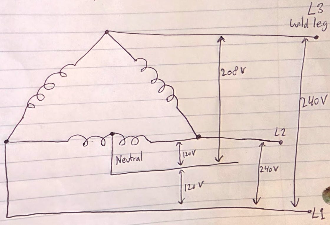
The closest existing solution is the high-leg delta transformer2 with a 240V secondary coil, often with one winding center-tapped for 120/240V service. Let’s say you are feeding 480V three-phase. Typical output voltage options: 120V single-phase, 208V single-phase, 240V single-phase, 240V three-phase. That’s a lot of options. A dedicated transformer is still necessary, and the voltages are asymmetric around neutral. Four-phase would provide the same options from the bus directly.
VFDs (motor speed controllers) rectify single-phase or three-phase input power into DC, smooth it on a DC bus, and then invert it back into controlled AC for the motor. Three-phase motors can still be used with four-phase input power with some changes to current VFDs (different input rectifier topology, using 8-pulse instead of the standard 6-pulse).
480V Delta to 240V Delta Transformer secondary coil side below: